Electrochemical Impedance at a Rotated Disk Electrode
Introduction
Whenever you read about Electrochemical Impedance, one of the first things they tell you is "The system must be stable and unchanging." Normally that means that you should run the EIS experiment at the Open Circuit Potential, where the DC current is zero.
Sometimes, though, you'd like to study the reaction when there IS a net current. A very relevant example is the study of catalysts for fuel cell or electrolyzer electrodes. Often, you'd like to study the catalyst under conditions very similar to that in an operating fuel cell, where the current density is large.
The Rotated Disk Electrode can come to the rescue! One of the nice things about the RDE is that the DC, mass transport controlled current is at Steady State, so it meets the stability criterion of EIS! It also has a sound theoretical basis.
Rotated Disk Theory
First, a word or two about the Rotated Disk Electrode.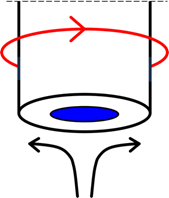
A sketch of the working end of an RDE is shown at the right. The disk electrode (blue) is embedded in a larger, non-conducting rod or shroud. The entire assembly is rotated. Solution is drawn up along the axis of rotation and past the electrode, so there is laminar (i.e., smooth) flow past the electrode surface.
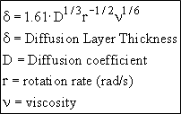 However, the solution at the surface is dragged along by the rotating disk, and there is a thin layer (the Nernst Diffusion Layer) that is unstirred. Within this layer, mass transport is controlled by diffusion alone. The effective thickness of this layer depends on the RPM of the rotator, the viscosity of the solution, and the diffusion coefficient of the electroactive species. As the rotation speed of the RDE is increased the Nernst Diffusion Layer becomes thinner.
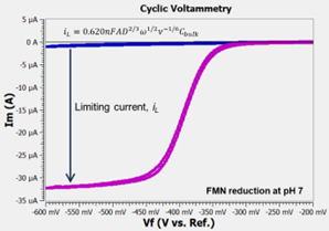
Another consequence of the NDL theory is that the current-voltage curve is S-shaped at scan rates below about 100 mV/s. The limiting current is given by the Levich equation. An example is shown to the right where flavin mononucleotide (FMN) is reduced at a glassy carbon RDE at neutral pH.
With all of THAT out of the way, we can begin to talk about ...
EIS at an RDE - the Porous Bounded Warburg
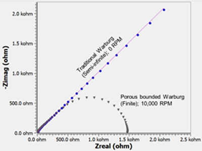
The hydrodynamics described above fits the requisites for a 'Porous Bounded Warburg': There is a thin layer of unstirred solution next to the electrode, and large, stirred, homogeneous source of material outside that layer. In between these regions there is a (virtual) membrane that is porous to the diffusing molecule. Some people refer to this equivalent circuit element as a Nernst circuit element because it fits the model of the Nernst Diffusion Layer. The porous bounded Warburg impedance is most easily recognized from its Nyquist plot. At high frequency, this circuit element looks like a traditional Warburg impedance and shows a 45° line on the Nyquist plot. At low frequency, it looks like the semicircle of a Randles Cell.
There is a short discussion of the Porous Bounded Warburg in Gamry’s EIS Primer.
 The Porous Bounded Warburg is characterized by two parameters, YO and B. The equation for Z is shown above, along with the gruesome definitions of YO and B. The parameter B (in sec1/2) is a measure of the time it takes for the reactant to diffuse across the Nernst Diffusion Layer. What is interesting is that B depends upon the NDL thickness, which in turn, depends upon the rotation speed (r) of the electrode!
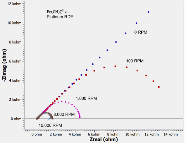
The results of a sequence of experiments at different rotation rates is shown below. The small semicircle at the higher frequencies (near Z=0) represents the double layer capacitance and the charge transfer resistance for the ferri-/ferro-cyanide reaction. The rotation rate-dependent arc at low frequencies (towards the right on the Nyquist plot, below), arises from the NDL. The equivalent circuit is shown below.
All of the data were fit to the same equivalent circuit model. We also show the B parameter of the Porous Bounded Warburg plotted vs. the inverse of the square root of rotation rate. As predicted, there is a nice, linear relationship over two orders of magnitude in rotation rate!
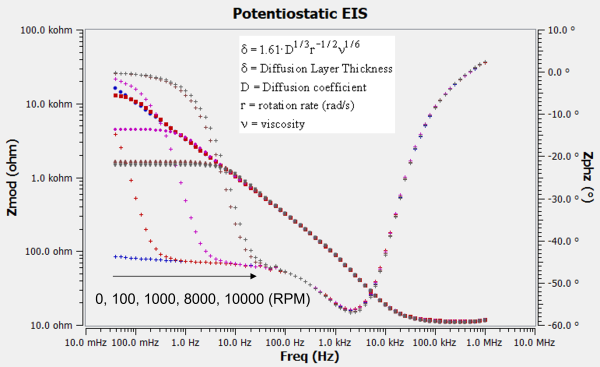
It’s worth noting that the charge transfer resistance can be small enough to appear negligible on the Nyquist plot. The plot above shows impedance spectra where the kinetics are fast enough such that nearly all the impedance is mass transport controlled. In this case, it is useful to look at the Bode plot shown further below to visualize the kinetics region. The phase angle shows the transition from the semi-infinite Warburg behavior to the porous bounded Warburg response. The transition occurs at higher frequencies as the rotation rate increases. This reflects the decrease in NDL thickness and that less time is required (i.e. higher frequency) for the concentration gradient to fully form. Alternatively, you may think of the NDL as the maximum diffusion layer thickness. At the highest mass transport controlled frequencies, the AC modulation does not allow sufficient time for the diffusion layer to grow to the maximum value. Thus a 45° phase angle is observed. At the highest rotation rates, the phase angle approaches the theoretical value of 0°, which confirms that we indeed have a porous bounded Warburg! It is also reassuring to know that the impedance does not change with rotation rate within the kinetics region (>100 Hz).
Summary
The rotated disk electrode is one more tool in your electrochemical toolbox. It is well founded in theory and can be used for simple voltammetric or potentiodynamic scans, as well as for impedance studies. When diffusion is modeled in an EIS experiment, the Porous Bounded Warburg or Nernst circuit element is the proper one to use and start with. There are alternative models that are more rigorous than the porous bounded Warburg, but we will leave that for a future application note. For simple systems, excellent fits can be obtained over a wide range of rotation rates using the Nernst circuit. Most importantly, varying the rotation rate can be one way to test the validity of your model!
References
Bard and Faulkner, "Electrochemical Methods", Wiley, 2001.
Macdonald, "Impedance Spectroscopy", Wiley, 1987.
M Boillot, S Didierjean, F Lapicque,"Impedance of a rotating disc electrode with a reversible reaction", J. Appl. Electrochem., 34 (2004) 1191-1197.
Want a PDF version of this application note?
Please complete the following form and we will email a link to your inbox!
Categories