Running EIS with an IMX8 Electrochemical Multiplexer
Purpose of This Note
This technical note provides baseline performance benchmarks for using a Reference 620 potentiostat (REF620) or Interface 1010E potentiostat (IFC1010E) paired with an IMX8 electrochemical multiplexer (IMX8) to run EIS tests.
Introduction
We assume the reader knows the basics of EIS. If this is not the case or the user wants to brush up on EIS, we recommend reading our white paper, here. Theoretical concepts of EIS will not be discussed in this note.
The IMX8
The IMX8 Multiplexer is a powerful measurement device. It is equipped with eight independent channels which enable higher throughput of electrochemical measurements. One cell at a time is accessed by the system potentiostat and electrochemical measurements can be performed. A special characteristic of the IMX8 is the local potentiostat. Each of the eight channels has its own local potentiostat that allows potential control of inactive cells between readings. The switching action between system potentiostat and the local potentiostat allows practically uninterrupted potential control of the sample or working electrode.

Figure 1. Overall system configuration for the IMX8 connected to up to eight (electrochemical) cells.
Note local potentiostats are built into the IMX8 and are not specifically called out here.
Compatible system potentiostats include either the IFC1010E or the REF620. The IMX8 shares the same form factor as the IFC1010E, which is shown in Figure 1. An interconnect cable passes signals between the IFC1010E and the IMX8. The red highlights in Figure 1 show where this cable connects to. Note the same cable is used to connect between a REF620 and IMX8.
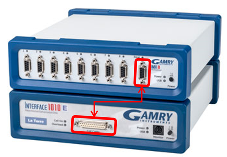 Figure 2 – The IMX8 on top of an IFC1010E with red markup showing where the interconnect cable is routed.
The IMX8, like all our potentiostats, is a USB-based instrument that is fully integrated into Gamry’s Framework acquisition software. All electrochemical applications or scripts included in Framework are allowed when using an IMX8. This includes creating complex test sequences using the Sequence Wizard.
Specifically, the IMX8, combined with a potentiostat, allows sequential measuring of EIS spectra. The measurement setup has to be built up just once and long-term tests can run without human intervention, reducing labor requirements and instrumentation costs.
Why EIS?
When done right, EIS is nondestructive to the investigated system. This allows combination with other techniques and the investigation of changes in a system with respect to time. Further, EIS allows the user to model the underlying system and the reaction mechanism. This contributes to a better understanding of the process and can lead to more precise results.
EIS, compared to other techniques such as cyclic voltammetry, is expensive. Being able to expand EIS testing capability through a multiplexer makes a good amount of sense! However, to have confidence in the EIS results, it is important for the user to know the limitations and specifications of the EIS system when connected through a multiplexer. The rest of this document discusses the impact of the IMX8 on EIS when connected to our IFC1010E or REF620.
Results and Discussion
The accuracy contour plot (ACP) for an EIS-capable potentiostat informs you about its ability to make accurate impedance measurements across a range of frequencies. We suggest learning about ACPs here before proceeding. ACPs are published and measured under standard conditions, including using a standard-length cell cable (60 cm) and a realistic AC amplitude (≤10mVrms). The EIS performance of a potentiostat is said to be “reduced” or “affected” when the ACP cannot be measured under the testing conditions. Usually, reduced EIS performance is caused by adding excess cabling beyond standard-length, improper grounding, or by adding inline connectors or devices (or what’s called a breakout box). The IMX8 can be considered to fall into the last category where it acts as an inline switch to run EIS across eight cells, one-at-a-time. However, because we designed it in-house, we tailored the IMX8 to be as transparent as possible when placed inline between the system potentiostat and the active cell. This should give you confidence that the multiplexed EIS tests that you run with an IMX8 maintain the highest achievable data quality. But what does “transparent” mean? We quantify this below.
First, we establish the baseline EIS performance by running tests solely on the system potentiostat, or the REF620 in this example. Figure 3 shows the measured impedances (Zmod) for 1 nF and 5 pF ceramic capacitors, measured individually, alongside an open lead spectrum. The open lead is shown as a reference point, where it is the absolute smallest capacitance, the system can measure without considering accuracy. Modeling the spectrum as a capacitor yields an apparent capacitance of ~0.14 pF, which we typically refer to as stray capacitance (Cstray). This very small Cstray is one of the reasons the REF620, by itself, excels under high impedance test conditions such as with barrier coatings.
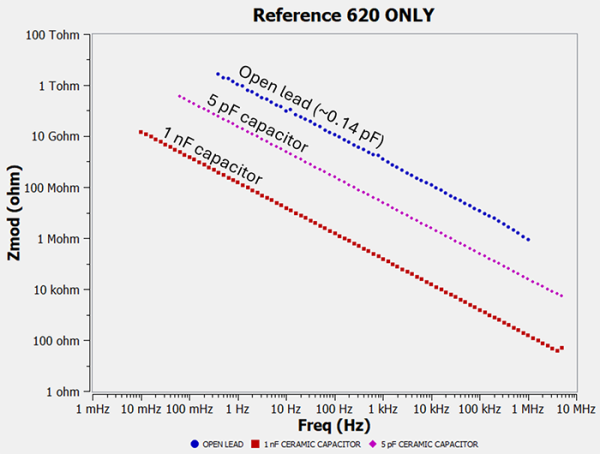
Figure 3. The measured impedance (Zmod)—using the REF620 alone—for open lead (blue symbols),
a 5 pF ceramic capacitor (magenta symbols), and a 1 nF ceramic capacitor (red symbols).
By itself, the REF620 excels in both high impedance and very small sample capacitance.
When an IMX8 is included inline, Cstray is expected to increase because of 1) additional shielded cabling (total 2m) and 2) inline IMX8 components such as relays. We measured the effective Cstray for the REF620+IMX8 pair as ~10 pF, which is about a 100x increase over the REF620 alone. Again, this is expected and is the reason why we don’t usually recommend the IMX8 for evaluation of barrier coatings (especially thicker applications!). A good rule-of-thumb is to limit measurements to within 10x to 100x larger than Cstray.
Capacitive samples
Following the above general rule-of-thumb, Figure 4 shows the measured impedance for a 1nF capacitor both with and without the IMX8. Looking at Zmod, there is no perceivable difference, and it is exactly what we’re looking for. Whereas Zphz shows slight distortion around the current range changes when the two spectra are compared. These phase distortions (see here for more details) are less than 1° and are therefore negligible. The results confirm our general rule-of-thumb that you should limit measurements to within 100x of Cstray, which is 1 nF for the REF620+IMX8 pair. We also tested a 100 pF ceramic capacitor and found phase distortions in excess of 5°, indicating that 100 pF is outside of the IMX8’s capability. Therefore, we suggest that users restrict capacitive sample impedance measurements to values greater than 1 nF.
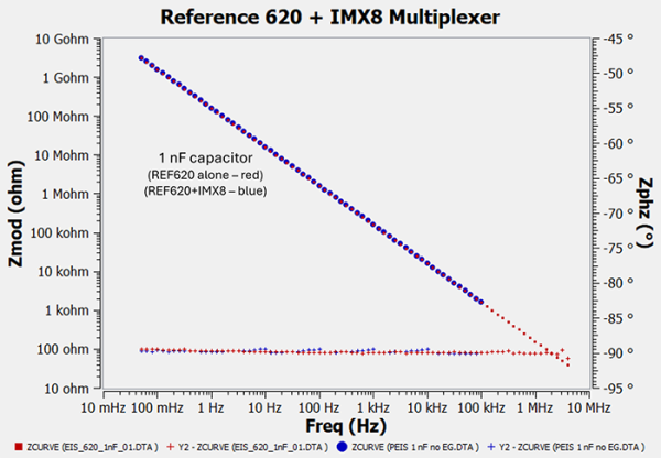
Figure 4. The measured impedance (Zmod, Zphz) of a 1nF ceramic capacitor for both the REF620 alone (red symbols)
and using the IMX8 paired with a REF620 (blue symbols). A small amount of phase error is observed when the IMX8 is used. However, it is <1°, and therefore negligible. Note that 100 kHz is the maximum allowable frequency for EIS on the IMX8.
Maximum impedance
Figure 4 also shows a value of about 3 Gohm was measured at the lowest frequency (50 mHz). This can be taken as the maximum impedance value for a REF620+IMX8 pair. To be safe, we suggest that the sample impedance (Zmod) does not exceed 1 Gohm. Note that the 100 pF capacitor test showed excess noise when Zmod exceeded >10 Gohm. Altogether, the high impedance upper limit for an IMX8 is a parallel RC pair consisting of a 1 nF capacitor and a 1 Gohm resistor. This is true whether you pair an IMX8 with a REF620 or a IFC1010E. Please keep in mind that these measurements use ideal resistors and capacitors. Behavior on real electrochemical cells may vary in unpredictable ways.
Low Impedance
The relays, or switches, in the IMX8 can carry currents up to 1.5A. This is why operation with a Reference 3000 potentiostat (3A max current) or the Interface 5000E potentiostat (5A max current) is not allowed. Users must be careful not to accidentally pass >1.5A through the IMX8. We recommend users consider the EIS Box 5000 as it is designed for multiplexed EIS in low impedance systems. Visit the EIS Box product page here.
REF620 or IFC1010E—which should I use with the IMX8 for EIS applications?
Here are some tips to decide:
- If you plan to always use the IMX8 and never plan to use the system potentiostat alone, we suggest you use the IFC1010E.
- Consider the REF620 if you plan to run single-channel measurements for validation before increasing testing throughput with an IMX8. As Figure 3 shows, high impedance with the REF620 is very good and extremely reliable.
- You can build up to a 32 channel multiplexed EIS test system by slotting several IFC1010E+IMX8 pairs into our Interface Power Hub. Four pairs can fit in total. The only question is whether you’re crazy enough to assemble 32 corrosion test cells!
Summary
The IMX8 is a cost-effective way to increase EIS testing throughput without compromising the quality of your impedance results. Yes, the working range of a REF620 or IFC1010E is reduced when paired with an IMX8, but this is both expected and can be accounted for. Please reach out to us if you have any questions or concerns about EIS through the IMX8.
Want a PDF version of this application note?
Please complete the following form and we will email a link to your inbox!
Categories