Measuring pA-level current flowing across artificial Ion channels and Nanopores Using a Reference 620 potentiostat
Authors: Yuhui Wang and Yuanwen Jiang
Jiang Group, University of Pennsylvania, Philadelphia, PA, https://jianggroup.seas.upenn.edu
(Edited by Gamry with added discussion on current accuracy and resolution)
Introduction
Ion channels and pores facilitate the transport of inorganic and organic molecules across lipid bilayers without displacing themselves or disrupting the membrane's suprastructure. Synthetic ion channels mimic their natural counterparts by embedding into lipid bilayers, forming pores, and enabling ion flow between two sides. As artificial analogs of natural ion channels, these synthetic structures hold significant promise paving the way for single-molecule sensing technologies and novel therapeutic applications.
There are two primary methods for characterizing synthetic ion channels and pores. Conductance experiments using planar or "black" lipid membranes (BLMs) help elucidate the electrical properties of the ion channel or hollow interior of a pore. Additionally, fluorescence spectroscopy with labeled large unilamellar vesicles (LUVs) offers insights into the influx and efflux of ions and molecules through these channels and pores. BLM experiments are essential for confirming the presence of an ion channel or pore and offer detailed mechanistic insights compared to LUV-based methods. Below, we briefly introduce the fundamental principles of BLM experiments and discuss how to use a Reference 620 potentiostat to measure single channel current for characterizing synthetic ion channels and pores.
Fundamental Principles
Precise measurements at the picoampere (pA) level are critical for advancing research in nanopore technologies, particularly for applications in biosensing, molecular analysis, and ion transport.
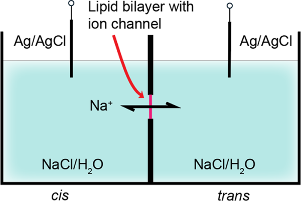
Figure 1. Schematic presentation of the experimental setup
for single-channel conductance measurements using a two-electrode configuration.
A conventional setup for characterizing synthetic ion channels and pores in BLMs consists of two chambers, referred to as cis and trans, which are filled with buffer solution (Fig. 1). The cis chamber is typically connected to the input electrode, while the trans chamber is connected to a reference electrode. A BLM is formed across a small aperture (micron-scale) separating the two chambers, functioning as an insulating barrier. In the absence of ion channels or pores, no current flows between the two electrodes because the transfer of anions and cations across the hydrophobic core of the lipid bilayer is impeded.
Synthetic ion channels and pores can be introduced into either the cis or trans chamber. By applying a repulsive voltage, they can be driven into the BLM positioned between the chambers. Once incorporated into the BLM, the current passing through the synthetic ion channel or pore is monitored and recorded over time.
Experimental Setup
- Nanopore Assembly:
A solution of diphytanoylphosphatidylcholine (diPhyPC) in chloroform (10 mg/mL, 20 μL) was evaporated with nitrogen gas to form a thin film and was re-dissolved in n-decane (20 μL). The lipid solution (0.5 μL) was injected onto the aperture (diameter = 200 μm) of a Delrin cup and evaporated with nitrogen gas flow. The lipid bilayer was formed by spreading lipid solution across the aperture. - Bilayer Formation and Stability Testing:
The chamber (cis side) and Delrin cup (trans side) were filled with aqueous NaCl solutions or buffer solution, and Ag/AgCl electrodes were applied directly to both solutions. The electrode in the cis side solution was grounded. Planar lipid bilayer formation was confirmed by monitoring capacitance (typically 80-150 pF for a stable bilayer). - Nano Channel or Nanopore Insertion:
The solution for the synthetic ion channel in DMSO (< 5 μL) was added to the cis chamber under stirring to reach a final concentration of 1 μM. Driven by hydrophobic and electrostatic interactions, the channel molecules were spontaneously incorporated into the lipid bilayer to form transmembrane channels. Note: Information on the specific compound to make the synthetic ion channel is withheld on purpose. It is of the crown-ether type. Please see the review paper cited here for more information. 1 - Measurement connections:
The Ag/AgCl electrode in the cis side solution was grounded and connected to the working/work sense leads of a Reference 620 potentiostat. The Ag/AgCl electrode in the trans side was connected to the counter/reference leads. In this two-electrode configuration, the potential was applied across the bilayer using the two Ag/AgCl electrodes. Using the chronoamperometry script, a constant voltage of either +50 mV, -50 mV, +150 mV, or -150 mV was applied across the bilayer to drive ionic current through the nanopore. Typical baseline currents ranged from a few pA to tens of pA, depending on the nanopore size and ionic conditions. Parameters used are shown in figure 2.
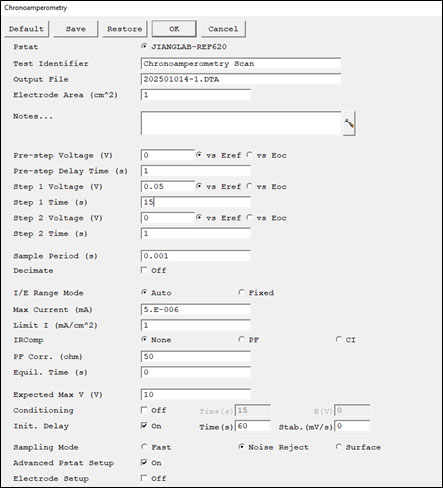
Figure 2. Setup window with parameters used for the single channel conductance test.
Results and Discussion
Single-channel currents exhibit stochastic on-off transitions (Fig. 3). These transitions represent the typical behavior of individual molecules, commonly referred to as single-molecule phenomena. Unlike macroscopic or "multichannel" behaviors, these single-channel events are not visible when observing the ensemble average.

Figure 3. Representative current traces of the planar lipid bilayers in the presence
of an artificial ion channel at applied voltages of: (a) +150 mV (b) +50 mV (c) -50 mV (d) -150 mV.
Asymmetric repetition or multiple current levels of varying magnitudes indicates the coexistence of two or more single ion channels or pores with distinct active structures (Fig. 3c). Such sample heterogeneity is more commonly observed in supramolecular ion channels and pores compared to unimolecular ones. Time-dependent sample heterogeneity may suggest the presence of one or more intermediates detectable during the formation of the final pore, as proposed in Engelman’s "two-state" model.2 While these subconductance levels offer intriguing possibilities, including conformational changes, counterion effects, and molecular recognition, identifying their exact structural origins is often challenging.
In contrast, without artificial ion channel present, no stochastic on-off transitions were observed under the same test conditions (fig. 4), implying that no regular transmembrane nanochannel/nanopores were generated. The silence of the bilayer to the applied voltage indicated that it was impermeable to Na+.

When the ON-current is averaged for the data shown in Figure 3, it is possible to estimate the conductance as shown in Figure 5. The sodium conductance (γNa+) was calculated to be 253 pS according to the obtained current-voltage (I–V) curves.
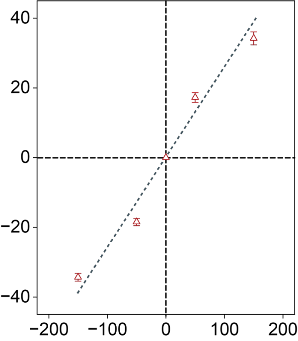
Figure 5. I–V plots recorded in symmetric baths
(cis chamber=trans chamber= 1 M NaCl)
for determining the sodium ion conductance (γNa+)
Troubleshooting
Several factors can contribute to the inability to detect single-channel currents for inserted synthetic ion channels or pores. These include:
- Incorrect lipid composition of the BLM, influenced by numerous variables.
- Incorrect lipid composition of the BLM, influenced by numerous variables.
- Insufficient partitioning of the synthetic ion channels or pores into the BLM due to small surface areas or excessive hydrophobicity.
- Inadequate transport rates that fall below detection thresholds.
The failure to detect single-channel currents does not necessarily indicate the absence of a synthetic ion channel or pore. Similarly, occasional detection of single-channel currents, even with reasonable reproducibility, does not conclusively confirm their presence. Small deviations or failures in the electrochemical cell setup (e.g. a bad electrode connection) can induce pA-level currents that could be incorrectly assigned as the nanochannel/nanopore response. Single-molecule experiments are particularly prone to artifacts like this, so complementary evidence from LUV experiments is highly recommended.
Potentiostat considerations (Contribution by Gamry)
It is also important to remember that the potentiostat settings must be accounted for. The Reference 620 potentiostat has two sensitive current ranges used for pA-level detection: 60 pA and 600 pA full scale current ranges. The accuracy error and resolution of a current measurement is calculated by:

When using the 60 pA current range, the error is calculated as ( 10 pA+0.3 pA + (0.015×Im) ) where Im is the measured current. Usually, the last term can be ignored, and the first term dominates with a small contribution from the middle term. The middle term, controlled by full scale current range, underscores why a Reference 620 potentiostat is warranted. If we instead used the Interface 1010E potentiostat with the smallest full scale current range of 10 nA, the middle term would be 5 pA, or an order of magnitude larger. In terms of absolute current accuracy and current resolution, the Reference 620 is unmatched. On the 60 pA current range, the smallest resolvable change in the measured value is 0.12 fA. Though you will not observe this in practice as the current noise in a real system often exceeds this value. It may be possible to observe it if the sampling frequency chosen greatly exceeds the frequency of the current noise.
There may also be a contribution to the measured current, Im, from the voltage noise in the applied potential signal, depending on the capacitance of the system (ideally the BLM in this case). Let’s assume voltage noise is 10 µVrms for the Reference 620 potentiostat. For convenience, let’s also assume the noise has a frequency of 60 Hz (line frequency). If the voltage noise is applied across the BLM capacitance, let’s assume 150 pF, then the resulting current (In) of the applied voltage noise will be In = Vn/Zcap ≈ 1×10⁻⁵ V/(2π×60Hz×1.5×10-10F)-1 ≈ 0.6 pA. From this simple calculation, one should expect the baseline current to vary if the BLM capacitance or voltage noise levels vary between replicates. This can be considered as a nonfaradaic contribution to the measured current, Im. Luckily, the Reference 620 specification for voltage noise is below 2 µVrms (typical).
Conclusion
This application note introduces and provides a framework for understanding and performing pA-level measurements of nanochannel/nanopores supported on lipid bilayers. These measurements can provide insights into the behavior of single molecules or ions passing through the nanopores, which is crucial for understanding molecular transport, sensing applications, and even genomic sequencing.
1 He, L., Zhang, T., Zhu, C., Yan, T. & Liu, J. Crown Ether-Based Ion Transporters in Bilayer Membranes. Chemistry – A European Journal 29, e202300044, doi:https://doi.org/10.1002/chem.202300044 (2023).1 He, L., Zhang, T., Zhu, C., Yan, T. & Liu, J. Crown Ether-Based Ion Transporters in Bilayer Membranes. Chemistry – A European Journal 29, e202300044, doi:https://doi.org/10.1002/chem.202300044 (2023).
2 Sakai, N., Houdebert, D. & Matile, S. Voltage-Dependent Formation of Anion Channels by Synthetic Rigid-Rod Push–Pull β-Barrels. Chemistry – A European Journal 9, 223-232, doi:https://doi.org/10.1002/chem.200390016 (2003).
Want a PDF version of this application note?
Please complete the following form and we will email a link to your inbox!
Categories